Trojan Part No. 55-077
Pages 1 thru 3
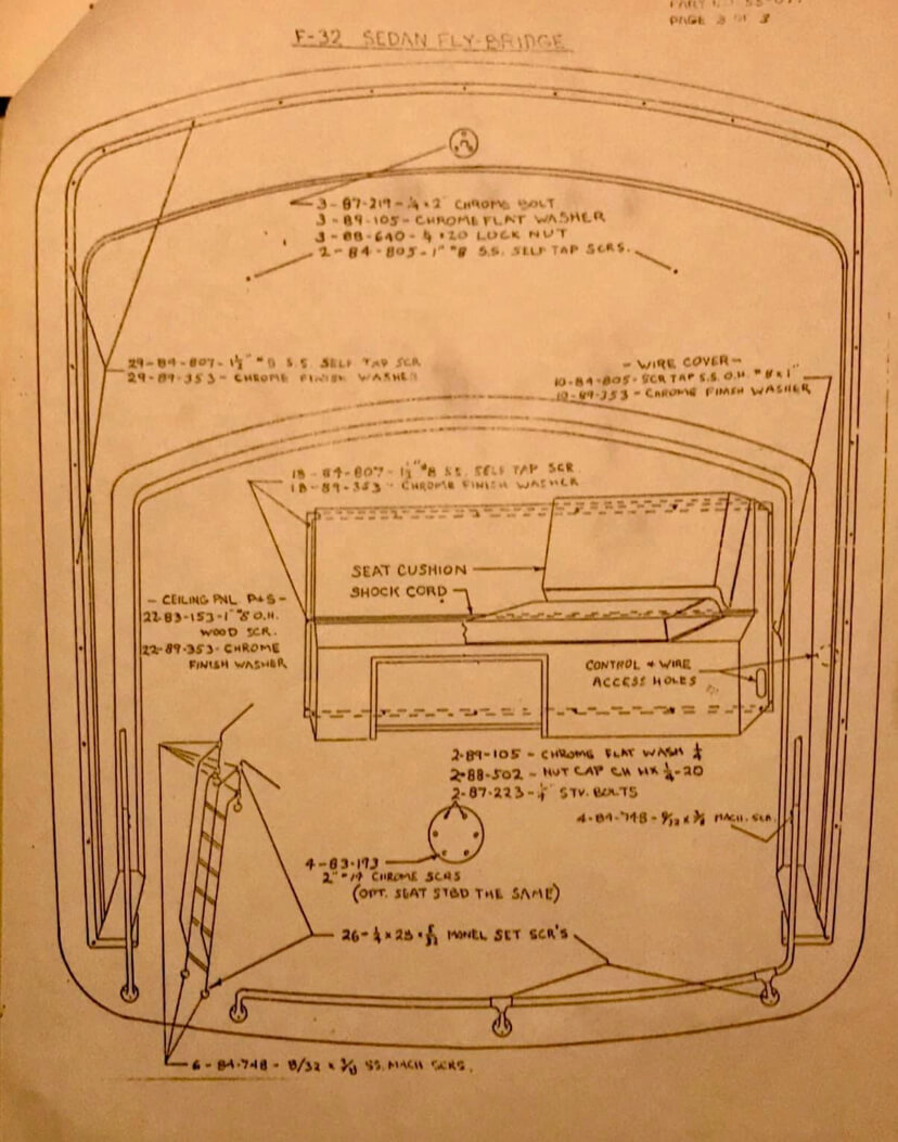
Note: All required fastenings for re-assembling the fly-bridge are packaged in one (1) carton marked “Fly-Bridge Fastenings”
and placed on board. Refer to the attached sketches for fastening locations.
1. Position the fly-bridge on the hard-top and fasten thru the fly-bridge base along the outboard flange into the hard-top roof using the supplied:
29 –---- Part No. 84-507 –----- 1-1/2" #8 S.S. Self Tapping Screws
20 –---- Part No. 89-353 –----- Chrome Finish Washers
Note: Apply the supplied compound, Part No. 71-021 to all mating surfaces where the bridge makes contact with the hard-top roof.
2. Compound and position the anchor/running light in the pre-drilled hole located in the center of the fly-bridge panel. Bolt thru the fly-bridge face panel and ceiling panel using the supplied:
3 –---- Part No. 87-219 –---- 1/2 x 20 x 2” Chrome Stove Bolts
3 –---- Part No. 89-105 –---- Chrome Flat Washers
3 –---- Part No. 88-640 –---- Self Locking Nut
Fasten the mast stays to the fly-bridge face panel using the supplied:
2 –---- Part No. 84-805 –---- 1" #8 S.S. Self Tapping Screws
Connect the mast light plug to the plug in the teak pad mounted on the hard top roof.
3. Position the port and starboard ceiling panels and fasten using the supplied:
22 –---- Part No. 83-153 –---- 1" #8 Chrome Oval Head Wood Screws
22 –---- Part No. 89-353 –---- Chrome Finish Washers
4. Apply compound to all the mating surfaces and position the control console aligning the pre-drilled holes
on the hard-top roof. Fasten thru the flange into the hard-top roof using the supplied:
18 –---- Part No. 84-807 ----- 1 ½” #8 S.S. Self-Tapping Screw
18 –---- Part No. 89-353 –---- Chrome Finish Washers
Note: Route the wire harness and control cables thru the hole in the starboard end of the control console.
Connect wire harness at the terminal blocks using supplied:
32 –---- Part No. 84-119 ----- 8/32 x 5/16 Scr Mach CH BH
5. Assemble steering.
Syten – tubing is marked with red, green and no tape. Connect disconnects.
6. Connect the shift and throttle control cables as marked to the aft arms on the control heads and adjust the linkage for proper operation.
Note: Be sure to tighten the lock nuts on the control cables when the adjustments are complete.
7. Make wire harness connections on the terminal block inside the helm console as per fly-bridge wiring diagram supplied with the boat.
8. Compound and position the helm seat aligning holes in the pedestal base with the pre-drilled holes in the hard-top roof.
Fasten thru the pedestal into the hard-top roof using the supplied bolts in the two forwardmost holes and the screws elsewhere.
2 –---- Part No. 87-233 ----- 1/2 x 4” Stove Bolts
2 –---- Part No. 82-505 ----- 1/2 x 4” Cap Nuts
2 –---- Part No. 87-824 ----- 1/4 Chrome Washers
4 –---- Part No. 85-191 ----- 1/4 x 2” O. H. Screw
9. Couple the stainless-steel handrails to the rail mounted on the fly-bridge sides (port and starboard) and fasten thru the pre-drilled and tapped holes using the supplied:
4 –---- Part No. 84-748 –---- 8/32 x 3/8” S.S. Machine Screws
Position the stanchions in the bases mounted on the hard-top roof, align and fasten using the supplied:
10 –---- 1/4 x 28 x 5/32 –---- Monel Set Screws (“Loctite” recommended)
10. Position the lower end of the fly-bridge ladder in the bases mounted on the cockpit deck and fasten using the supplied:
4 –---- 1/4 x 28 x 5/32 –---- Monel Set Screws (“Loctite” recommended)
2 –---- Part No. 84-748 –---- 8/32 x 3/8" S.S. Machine Screws
11. Align the fly-bridge ladder hand rails at the tee sockets and fasten using the supplied:
12 –---- 1/4 x 28 x 5/32 –--- Monel Set Screws (“Loctite” recommended)
4 –---- Part No. 84-748 –---- 8/32 x 3/8" S.S. Machine Screws
12. Install the control console seat cushions using the pre-assembled shock cord to hold them in position.
Refer to the attached sketch.
Note: For access to console compartment, remove the inside screws from
top batten of door track. This will free the track and doors for removal.
13. Install the wire cover parts between the console and the starboard ceiling panel using:
10 –---- Part No. 84-805 – Screw Tap S.S. O.H. #8 x 1"
10 –---- Part No. 89-853 – Chrome Finish Washers
14. Use the supplied gray putty tape (Part No. 71-028) to seal around cables and tubing in the starboard salon locker floor.